
This guide explains how to approach VRF sizing for commercial buildings, what information should be included in the load calculation, how indoor and outdoor units are selected, and which manufacturer-specific constraints can change the final selection.
Key Takeaways
- Proper VRF sizing starts with calculating heating and cooling loads for each zone.
- Diversity factor lets you choose a smaller outdoor unit than the sum of indoor units.
- Piping length and height limits reduce capacity, so always check manufacturer guidelines.
- Oversizing causes humidity problems, while undersizing leads to discomfort and strain.
- Use load calculation software and manufacturer tools for accurate VRF sizing.
VRF System Sizing Basics
How VRF Systems Work
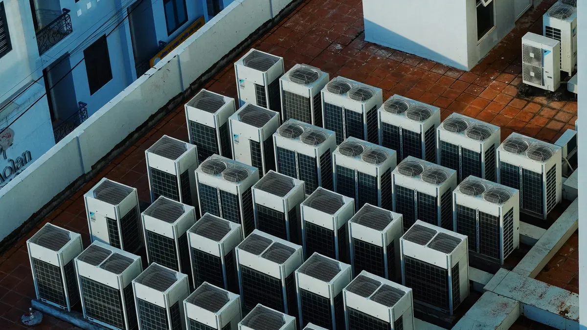
Variable refrigerant flow (VRF) systems use refrigerant as the primary heat exchange medium. One outdoor unit connects to multiple indoor units through refrigerant piping. Each indoor unit serves a separate zone within the building. Every zone has its own thermostat. Occupants set their preferred temperature independently. One zone can cool while another zone heats. This ability to provide simultaneous heating and cooling is a key advantage of this technology.
The compact nature of VRF units gives architects and engineers more options for usable space. Small mechanical rooms, ceiling plenums, or outdoor walls can house this equipment. This flexibility helps building owners adapt to changing needs. The inverter-driven compressor adjusts capacity to match exact load requirements.
Why Sizing Matters
VRF systems have strong adoption in the commercial market. Building owners recognize the value of precise zone control and energy efficiency.
VRF systems are most cost-effective in multi-zone buildings. Multi-zone buildings benefit most from this approach. Multi-zone systems allow different zones to maintain their own temperature setpoints. Each zone has unique load requirements based on occupancy, equipment, and sunlight. Correct vrf system sizing matches outdoor unit capacity to those combined loads. Proper sizing improves overall efficiency. An oversized unit short-cycles. It turns on and off too often, wasting energy and hurting humidity control. An undersized unit runs constantly. It cannot meet comfort targets during peak conditions. Energy efficiency drops in both scenarios. Attention to hvac systems design prevents these problems.
Design teams account for diversity during the sizing process. Not every zone reaches peak load at the same time. The outdoor unit can be smaller than the sum of individual indoor capacities. Piping length and height limits also affect the final selection. A qualified hvac professional uses load calculation software to determine exact needs. The result is steady comfort control with minimal waste. Light commercial vrf systems offer similar benefits for smaller properties.
Important: VRF sizing cannot be determined reliably from floor area or a generic kW-per-square-meter rule alone. Final equipment selection depends on the calculated building load, design conditions, indoor and outdoor unit combination, refrigerant piping configuration, elevation, and manufacturer-specific performance data.
Step-by-Step VRF Sizing Process
Calculating Loads
A sound variable refrigerant flow design follows four steps. First, select the system type. Choose between heat pump and heat recovery based on simultaneous heating and cooling needs. Second, address humidity control. Third, plan ventilation. Fourth, size the equipment.
Load calculation comes first within the sizing step. For commercial load calculations, ACCA Manual N provides procedures for determining heating and cooling loads, including envelope, internal, infiltration, and ventilation loads. ANSI/ASHRAE/ACCA Standard 183-2024 establishes minimum requirements for peak heating and cooling load calculations in buildings except low-rise residential buildings. The ASHRAE Handbook—Fundamentals provides additional technical guidance for heat transfer and load calculation methods. Preliminary rules of thumb based on floor area may be useful for early budgeting, but final equipment selection should be based on a detailed load calculation and manufacturer performance data.
What Should Be Included in a VRF Load Calculation?
| Load factor | Why it matters |
|---|---|
| Outdoor design conditions | Determines peak design load |
| Building envelope | Walls, roof, floor and thermal insulation |
| Windows and solar exposure | Affects solar heat gain |
| Occupancy | Adds sensible and latent heat |
| Lighting and equipment | Adds internal heat gain |
| Ventilation | Adds sensible and latent load |
| Infiltration | Adds outdoor air load |
| Room usage schedule | Determines when zones peak |
Selecting Indoor and Outdoor Units
Indoor unit selection proceeds zone by zone. Each zone receives an indoor unit based on its calculated design load and the manufacturer’s available capacity range. The combined indoor-unit capacity is then compared with the calculated system load and the manufacturer’s permitted indoor-to-outdoor connection ratio.
Diversity describes the difference between the sum of individual zone peak loads and the expected simultaneous peak load of the system. Because different zones do not necessarily reach their maximum load at the same time, the system-level peak demand can be lower than the sum of the individual zone peaks.
This concept should not be confused with the indoor-to-outdoor unit connection ratio, which is a separate equipment-selection parameter defined by the manufacturer. The appropriate combination must be verified using the selected manufacturer’s engineering data or selection software.
A worked example clarifies the math. Suppose a building has 40 kW of connected indoor capacity and a diversity factor of 0.85. The effective simultaneous demand is 34 kW. An outdoor unit rated at 36 kW yields a sizing ratio of 1.06, an optimized match. Ignoring diversity would wrongly suggest a larger outdoor unit. Another method divides total indoor capacity by the diversity factor. With 100 kW of indoor capacity and a factor of 1.3, the outdoor unit sizes at approximately 77 kW. This works because spaces rarely reach peak load at the same moment. Combining zones with different solar exposures on one outdoor unit raises cooling load diversity.
Piping limits constrain the final selection. Longer runs with high equivalent length require derating the outdoor unit’s effective capacity. Elevation differences between indoor and outdoor units impose additional limits. Typical maximums appear below.
Refrigerant Piping and Elevation Limits
Refrigerant piping must be checked as part of the final VRF equipment selection. Total equivalent piping length, the longest actual pipe run, vertical separation, branch configuration, and other installation conditions can affect the allowable system configuration and available capacity.
These limits are not universal across VRF systems. Always use the engineering data for the selected manufacturer and product series to verify piping requirements and any applicable capacity correction factors.
Always confirm these values against the specific manufacturer manual. Exceeding them can cause oil imbalance and control instability. A qualified hvac professional checks every run against the OEM guidelines before finalizing equipment. This discipline protects energy efficiency and keeps temperature steady across all zones.
Key Factors in Variable Refrigerant Flow Sizing
Several factors influence the final capacity during VRF system sizing. Building orientation, insulation quality, ventilation demands, and diversity shape the load calculation. VRF systems require careful evaluation of each factor. Proper design accounts for these conditions. Ignoring them leads to poor comfort and wasted energy.
Building Orientation and Insulation
The position of a building on its site affects cooling loads directly. South-facing and west-facing rooms receive more intense sunlight. These zones require larger indoor units to handle the extra heat gain. Poor thermal insulation raises the cooling load as well. Large glass areas allow more heat transfer into the space. Both factors increase the calculated load for the VRF system. Design professionals account for these conditions in every zone.
The table below summarizes these building characteristics and their effects on VRF load calculations.
| Factor | Effect on VRF Load Calculation |
|---|---|
| Building orientation | South and west facing rooms need higher cooling capacity due to greater sunlight exposure. |
| Insulation and glass area | Poor insulation and large windows both increase the cooling load. |
Accurate load data helps VRF systems perform efficiently. The result is a properly matched VRF system that maintains comfortable temperature throughout the year.
Ventilation and Diversity
Ventilation introduces outside air into the building. This outdoor air carries its own heating and cooling demands. Humid outdoor air adds a latent load that the VRF system must handle. Proper humidity control protects occupant comfort and prevents mold growth. HVAC design must include dedicated outdoor air systems or integrated ventilation strategies.
Diversity factor plays a major role in sizing decisions. Not every zone reaches peak load at the same time. Commercial buildings illustrate this pattern well. An office building might see full cooling demand on the west side only in late afternoon. The east side peaks in the morning. The outdoor unit can be smaller than the sum of all indoor units. This approach improves overall efficiency.
Piping length and height limits also require attention. Longer refrigerant runs reduce effective capacity. Elevation differences between indoor and outdoor units require careful planning. Manufacturers provide specific limits for total equivalent length, longest single run, and vertical separation. Exceeding these limits causes oil return problems and reduces energy efficiency. A qualified HVAC professional checks every run against these limits. Proper VRF systems design follows these constraints.
These factors together determine the final selection. Attention to building characteristics, ventilation needs, and diversity ensures steady temperature across all zones.
Common VRF Sizing Mistakes
Oversizing and Undersizing
Oversizing is a frequent error in humid climates. An oversized unit quickly reaches the temperature setpoint. It does not remain in the latent cooling range long enough to remove meaningful moisture from the air. Humidity stays high even though the space feels cool. This condition causes discomfort, condensation, and indoor air quality problems. According to the HVAC School podcast, it is Neither deliberate oversizing nor undersizing is an appropriate design strategy. Equipment selection should be based on calculated design loads, manufacturer performance data, and the system’s operating conditions. Properly sized or undersized systems run longer and dehumidify more effectively. Undersizing carries its own risks. An undersized unit runs constantly and cannot meet comfort targets during peak conditions. Equipment strain shortens the life of the system. Both errors hurt energy efficiency and raise operating cost.
Ignoring Piping and Ventilation
Piping limits directly affect capacity. The total cooling load delivered to terminal units is reduced after piping losses are accounted for. The equivalent pipe length between the farthest terminal unit and the heat pump condenser includes gas line length, fitting losses, pipe bends, and other connections. This value drives the piping correction factor in cooling mode.
Neglecting ventilation and humidity control is another mistake. These steps belong to the four-step design process. Skipping heat recovery versus non-heat recovery selection also affects sizing and mode changeover. A qualified hvac professional checks every run and every load before finalizing equipment.
Tools for Accurate VRF Systems Sizing

Software and Load Tools
Load calculation software forms the foundation of accurate sizing. ACCA Manual N and ASHRAE Standard 183 guide the load calculation process for commercial buildings. These standards ensure the calculated building load matches real conditions across all zones. Manufacturer-specific selection tools then take over. Each program accounts for pipe length, fitting losses, and elevation differences between units. Refrigerant piping for a vrf installation cannot use generic pipe sizing tables. Each manufacturer’s system has unique oil management and pressure requirements. Generic tables cannot account for these differences. The manufacturer’s proprietary software produces confirmed pipe sizes for every segment of the refrigerant circuit. It also generates correction factors for total system capacity based on the specific piping configuration. This process ensures the outdoor unit meets the simultaneous peak load while accounting for piping length and elevation. The software provides a confirmed outdoor unit selection with verified performance data for the project’s outdoor operating conditions. These tools protect efficiency by matching equipment to real constraints. Reliable system selection depends on combining accurate load data with manufacturer-specific performance calculations.
Manufacturer and Professional Support
Professional assessment adds another layer of accuracy. Local equipment representatives provide quick sizing rules for initial estimates. Final sizing requires manufacturer guidelines and professional judgment. The ASHRAE course covers nonmanufacturer-specific concepts for vrf systems. It addresses system behavior, controls logic, refrigerant dynamics, and commissioning strategy. This course targets mechanical engineers, design-build contractors, and hvac systems designers. Brand-neutral training programs through the NATE 430 series cover vrf architecture and installation discipline. Commissioning uses factory-spec startup procedures and manufacturer diagnostic tools. These include refrigerant charge verification, communication bus testing, and zone-by-zone performance validation. Professionals with this training deliver better vrf results for commercial hvac design. Certification programs keep installers updated on new technologies and methods. Building owners should verify credentials and past project history before selecting an installer. Successful VRF projects require both engineering analysis and manufacturer selection tools. The vrf selection process accounts for every building constraint. A qualified installer combines these resources for reliable system performance.
Proper vrf system sizing follows a clear sequence. Calculate the building heating and cooling loads first. Select indoor units for each zone. Choose the outdoor unit. Account for diversity and piping limits. Each step in this process builds on accurate load data and careful planning. A disciplined approach prevents common mistakes.
Professional assessment ensures strong results. Qualified HVAC professionals use load calculation software and manufacturer selection tools. These resources match equipment to real-world conditions. The outcome is steady comfort and high efficiency. Accurate tools make the difference between good and poor performance.
Apply these steps to your next commercial project. A well-sized system delivers reliable performance year after year.
vrf systems work best when sized correctly.
How George Approaches Commercial VRF Projects
For commercial VRF projects, George approaches system selection from the building requirements rather than selecting equipment based only on nominal capacity.
The process begins with understanding the project conditions, including building usage, zoning requirements, cooling and heating loads, and operating schedules. The equipment configuration is then evaluated based on indoor unit selection, outdoor unit capacity, refrigerant piping layout, elevation differences, and manufacturer engineering data.
This approach helps ensure that the selected VRF system matches the actual requirements of the project and supports reliable long-term operation.
FAQ
Can I size a VRF system based on floor area?
No. Floor-area rules can be used for preliminary budgeting, but final VRF selection should be based on a calculated room-by-room load and manufacturer performance data.
How much larger can the indoor unit capacity be than the outdoor unit?
It depends on the manufacturer, product series, operating conditions, and local design requirements. Always verify the permitted indoor-to-outdoor combination ratio in the manufacturer’s engineering data.
Does longer refrigerant piping reduce VRF capacity?
Yes. Refrigerant piping length, elevation, branch configuration and operating conditions can affect available capacity. The correction must be taken from the selected manufacturer’s engineering data rather than a universal percentage.