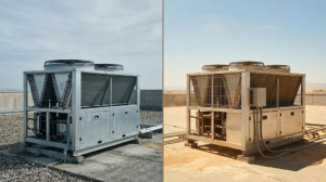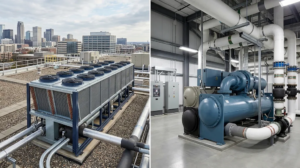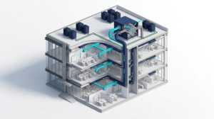
The stakes are increasing. The International Energy Agency estimates that global electricity demand for space cooling reached approximately 2,900 TWh in 2025, 50% higher than in 2015. This figure covers space cooling in buildings and excludes data centers. It is a market-level indicator—not a prediction of savings for any particular project—but it shows why better system design and operation matter. IEA, 2026
This guide explains how consultants, contractors, developers, and facility teams should coordinate VRF with DOAS and ERV equipment, from the design basis through commissioning and handover.
Key Takeaways
- VRF, DOAS, and ERV are not interchangeable. VRF primarily conditions recirculated zone air; a DOAS delivers conditioned outdoor air; an ERV transfers energy between outdoor and exhaust airstreams.
- Start with the project’s ventilation and humidity requirements. Do not select equipment from nominal airflow or nominal tonnage alone.
- Allocate sensible, latent, and ventilation loads explicitly. The design should state which system handles each load under peak and part-load conditions.
- Write one integrated control sequence. Temperature, humidity, outdoor airflow, exhaust, pressure, alarms, and failure states must work together.
- Commission the integrated system, not just individual units. Measured airflow and witnessed functional tests are essential.
1. Understand the Role of Each System
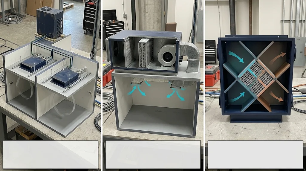
Most standard VRF indoor terminals primarily recirculate room air. They modulate refrigerant flow to meet zone heating and cooling demands, but their presence alone does not establish the required outdoor-air airflow. If outdoor air is connected directly to a VRF indoor unit, the project team must verify the manufacturer’s allowable entering-air conditions, capacity corrections, humidity limits, and control sequence.
A DOAS is a system dedicated to delivering outdoor air at the required airflow and supply condition. Depending on the design, it may include filtration, energy recovery, cooling, heating, dehumidification, reheat, supply and exhaust fans, and controls.
An ERV is equipment that transfers heat—and, depending on the energy-exchange device, moisture—between outdoor and exhaust airstreams. It can reduce the heating or cooling load associated with ventilation, but an ERV by itself does not define the required ventilation rate, supply-air dew point, building pressure, or code compliance.
| System | Primary role | What the project team must still verify |
| VRF indoor and outdoor units | Zone temperature control and recirculated-air heating/cooling | Residual latent load, minimum turndown, defrost, piping and ambient corrections, ventilation interface |
| DOAS | Required outdoor-air delivery at a controlled supply condition | Airflow, leaving-air temperature and dew point, dehumidification, reheat, fan power, part-load operation |
| ERV | Sensible and, where applicable, latent energy recovery between airstreams | Test conditions, supply/exhaust airflow ratios, leakage, frost control, bypass, filtration, fan and pressure requirements |
| Exhaust and relief systems | Remove contaminated or excess air and support pressure control | Bathroom, kitchen, laundry, garage and process exhaust; makeup air; pressure relationships |
| BMS and local controls | Coordinate operation and provide alarms and trends | Ownership of each control function, priorities, sensor failures, communication loss and restart behavior |
For a refresher on equipment architecture, see George’s VRF system fundamentals. The rest of this article focuses on the outdoor-air and delivery issues that remain after the basic VRF concept is understood.
2. Establish the Design Basis Before Selecting Equipment
A manufacturer’s selection program cannot resolve an incomplete design basis. Before comparing equipment, the project team should document the following.
2.1 Applicable codes and standards
Identify the jurisdiction, adopted ventilation and energy codes, local amendments, occupancy classifications, and the required standard editions. Where applicable, ASHRAE Standard 62.1 provides a framework for ventilation design, installation, commissioning, and operation and maintenance. Its use does not replace local code review.
Record the required outdoor-air calculation for every space type, including the applicable people and area components, occupancy density, ventilation effectiveness, system type, and any permitted demand-control strategy. Do not copy a ventilation rate from a previous project without checking the space and adopted edition.
2.2 Weather and indoor design conditions
At minimum, document:
- Summer outdoor dry-bulb and coincident wet-bulb or humidity data.
- Outdoor dew-point conditions relevant to dehumidification.
- Winter heating and humidification or frost-control conditions.
- Indoor temperature and relative-humidity or humidity-ratio targets.
- Altitude, rooftop heat exposure, recirculation risk, and other site-specific conditions.
A nominal “35 °C summer” description is not enough to determine the outdoor-air latent load. Two locations with the same dry-bulb temperature can require very different dehumidification capacity.
2.3 Occupancy, schedules, and exhaust
Map occupied, unoccupied, setback, housekeeping, event, and emergency operating modes. Include bathroom, kitchen, laundry, and process exhaust, together with door undercuts or transfer-air paths where relevant.
For hotels and similar buildings, distinguish sold, unsold, occupied, and unoccupied rooms. A key-card signal or property-management-system status should not automatically be treated as proof of actual occupancy.
3. Allocate Sensible, Latent, and Ventilation Loads
Every load should have an owner on the design documents. Otherwise, two common errors occur: the outdoor-air load is omitted, or it is counted in both the VRF and DOAS selections without a clear control strategy.
| Load or function | Typical primary responsibility | Coordination required |
| Zone sensible cooling and heating | VRF terminals and outdoor units | Account for DOAS supply-air temperature, internal gains, solar loads, and part-load operation |
| Outdoor-air sensible load | DOAS cooling/heating coil, potentially reduced by energy recovery | Define entering- and leaving-air conditions and whether supply air is neutral, cool, or warm |
| Outdoor-air latent load | Usually the DOAS dehumidification function | Verify coil condition, leaving-air dew point, reheat, and moisture removed by energy recovery |
| Indoor-generated moisture | VRF, DOAS, or a coordinated combination | Include occupants, showers, cooking, laundry, infiltration, and wet processes |
| Required outdoor airflow | DOAS/ERV fans and air-distribution system | Measure minimum and design airflow; verify distribution to each occupied zone |
| Exhaust and pressure | Exhaust fans, ERV/DOAS, relief and transfer paths | Check supply/exhaust imbalance under every operating mode |
| Zone temperature | Usually VRF | Prevent dehumidification or ventilation control from causing overcooling or overheating |
The VRF selection should then be checked against zone loads, simultaneous system loads, indoor-to-outdoor unit combinations, ambient conditions, refrigerant piping, elevation, and manufacturer performance data. George’s commercial VRF sizing guide explains those equipment-selection inputs in more detail.
Important: There is no universal rule that the DOAS must handle every latent load, or that the VRF system should handle all outdoor-air dehumidification. The correct allocation depends on the climate, internal moisture sources, supply-air strategy, equipment capabilities, and part-load controls.
4. Design for Humidity at Peak and Part Load
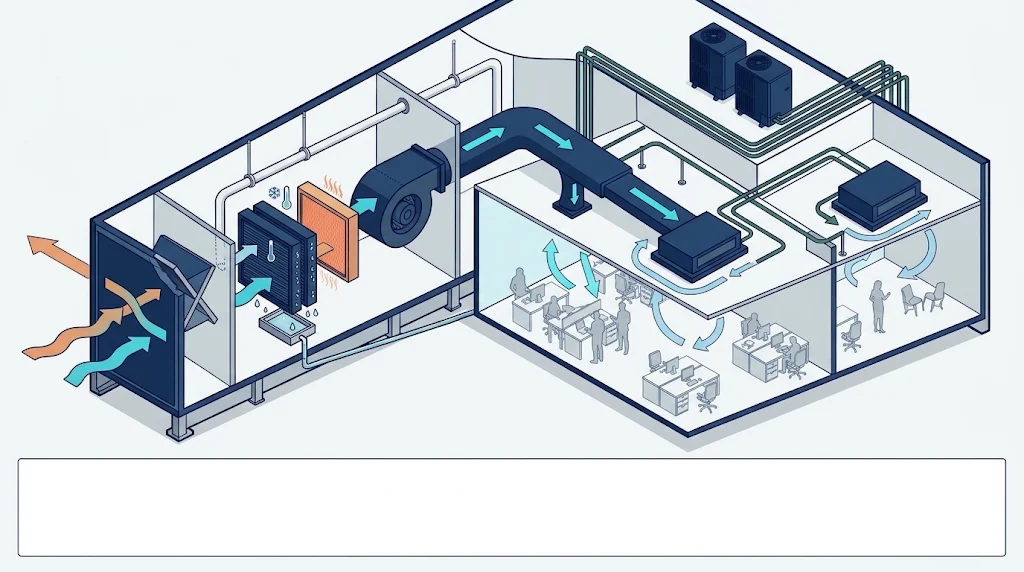
Temperature-only selection is one of the most common causes of discomfort in humid climates.
4.1 Calculate the outdoor-air load on a psychrometric basis
For an untreated outdoor-air stream, total cooling load can be approximated from mass flow and the enthalpy difference between outdoor and target supply air:
Q = ṁ × (h_outdoor − h_supply)
Use consistent units and separate the result into sensible and latent components where required. When energy recovery is used, determine the condition entering the downstream coil from tested performance at the project’s airflow and operating conditions. Do not apply one advertised “total efficiency” independently to dry-bulb temperature and humidity ratio.
4.2 Specify a supply condition, not just a coil capacity
The DOAS selection should state the required leaving-air temperature and humidity condition at summer design, part load, and other relevant operating points. A cooling coil may remove moisture while delivering air colder than the space requires. Reheat may then be necessary to maintain humidity without overcooling.
Reheat is not inherently a design failure. Uncontrolled reheat, simultaneous cooling and heating caused by conflicting sequences, or a coil that cannot maintain its leaving-air condition at low airflow may be. Evaluate the complete control sequence and annual operating profile.
4.3 Check low-load moisture risk
At low sensible load, a VRF terminal may satisfy the thermostat quickly and reduce operation while moisture continues to enter through ventilation, infiltration, or indoor sources. Possible responses include DOAS-led dehumidification, controlled reheat, adjusted supply airflow, or a revised load allocation. The response must be selected for the project—not copied from a generic sequence.
4.4 Review condensation and drainage
Confirm condensate capacity, trap design, drainage slope, insulation vapor sealing, and cold-surface temperatures. A unit that meets its nominal cooling capacity can still create moisture damage if drainage or insulation is poorly coordinated.
5. Select the DOAS/ERV Using Project Conditions
5.1 Energy-recovery performance
Request sensible and latent effectiveness at clearly stated test conditions, together with supply and exhaust airflow, pressure drop, fan power, and the test standard used. Review cross-leakage or carryover where exhaust contaminants are a concern. Commercial selections require project-specific engineering data rather than a generic recovery percentage or a residential climate rule of thumb.
Where certification is required or used as a procurement criterion, verify the exact model and rating conditions in the AHRI Directory of Certified Product Performance or the applicable certification directory. A generic brand claim is not evidence that every offered configuration is certified.
5.2 Coil and supply-air performance
Request cooling, heating, and reheat capacities at the actual entering-air and water/refrigerant conditions. Include minimum stable airflow, turndown, leaving-air temperature and dew point, defrost where relevant, and any capacity correction required by altitude or outdoor conditions.
5.3 Fans, filtration, and maintenance
Fan selection must account for filters, energy-exchange media, coils, ductwork, grilles, dirty-filter allowances, and the required external static pressure. Confirm motor power and control range rather than treating fan energy as a secondary issue.
Provide safe access to filters, cores or wheels, coils, fans, sensors, drains, and electrical components. A concealed unit that cannot be serviced without destructive ceiling work creates a long-term operating problem.
5.4 Frost, bypass, and exhaust suitability
Cold-climate projects require a defined frost-prevention and defrost strategy. Projects with contaminated, grease-laden, or corrosive exhaust require a suitable exhaust path and energy-recovery arrangement. Do not route kitchen hood exhaust through a standard energy-recovery core unless the complete assembly is specifically designed and approved for that application.
6. Write One Integrated Control Sequence
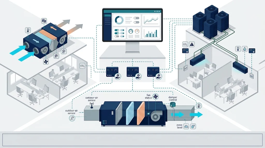
A controls drawing that only says “VRF and ERV connected to BMS” is not a sequence of operation. The design should identify which controller starts each fan, changes each mode, resets each setpoint, and generates each alarm.
The following is an illustrative framework, not a universal sequence:
- Scheduled start: Verify the required operating mode, outdoor-air path, exhaust interlocks, and sensor status before occupied operation.
- Zone temperature control: VRF terminals maintain their zone setpoints within the permitted operating range.
- Outdoor-air control: The DOAS/ERV provides the calculated outdoor airflow and resets it only where the adopted design permits.
- Humidity control: The responsible dehumidification component maintains the specified supply or space humidity condition; reheat is coordinated to prevent overcooling.
- Pressure and exhaust: Supply, exhaust, relief, and transfer-air operation are checked across normal and setback modes.
- Failure response: Fan failure, low airflow, sensor fault, high humidity, communication loss, and power restoration produce defined alarms and safe operating states.
- Trend review: The facility team can review temperature, humidity, airflow proxies or measurements, damper commands, fan status, operating mode, and alarms over time.
Use CO₂ carefully
CO₂-based demand-controlled ventilation can be useful in appropriate applications, but a single concentration is not a universal indicator of adequate ventilation or overall indoor air quality. ASHRAE’s 2025 position document on indoor carbon dioxide states that Standard 62.1 does not provide a general indoor CO₂ limit and emphasizes the effects of space type, occupancy, air distribution, and sensor performance.
Therefore, do not specify “ventilation is adequate below 1,000 ppm” as a blanket rule. Define the design ventilation rate, the DCV sequence, sensor locations and calibration, outdoor reference where needed, minimum airflow, non-occupant contaminant sources, and behavior during sensor failure. Energy-code requirements for DCV and energy recovery also depend on the adopted edition and application; review the relevant requirements rather than assuming that every space needs the same strategy. ASHRAE 90.1-2022 changes
7. Commission and Hand Over the Integrated System
Commissioning should verify that the combined system meets the owner’s requirements—not merely that each fan and compressor starts.
Where the project follows ASHRAE commissioning guidance, the Owner’s Project Requirements (OPR), Basis of Design (BoD), issue resolution, systems manual, and training should be coordinated from design through occupancy. The scope of ASHRAE Guideline 1.1 provides a useful framework for that process.
A 2020 Lawrence Berkeley National Laboratory meta-analysis covered 1,482 buildings and approximately 34.7 million m². For existing-building commissioning, it reported a median simple payback of 1.7 years, with a 25th–75th percentile range of 0.8–3.5 years. Outcomes varied by delivery mechanism and market segment. These results support the value of commissioning as a process; they do not justify promising the same savings or payback on an individual VRF/DOAS project. LBNL study
7.1 Installation and start-up records
Depending on the project scope, collect:
- Approved submittals and verified equipment models.
- VRF pressure-test, evacuation, refrigerant-charge, addressing, and communication records.
- DOAS/ERV duct, drain, insulation, filter, core/wheel, fan, and controls checks.
- Sensor calibration or verification records.
- Outdoor-air and exhaust-air measurement reports.
7.2 Functional and integrated tests
| Test | What to verify |
| Outdoor-air delivery | Required airflow at minimum and design operation; distribution to occupied zones |
| Exhaust and pressure | Exhaust airflow, relief/transfer paths, and pressure behavior across operating modes |
| Cooling and dehumidification | Entering/leaving conditions, leaving-air dew point where specified, coil and reheat response |
| Part-load operation | Stable control at low sensible load and reduced occupancy without uncontrolled humidity |
| VRF integration | Zone response, mode changes, defrost where observable, and no conflict with DOAS operation |
| DCV and sensors | Correct response within the approved sequence; sensor location and fault behavior |
| Alarms and failures | Fan failure, low airflow, high humidity, communication loss, and power restart |
| Seasonal tests | Conditions that cannot be verified during the initial site visit are scheduled and closed later |
7.3 Handover and baseline
Provide as-built drawings, final setpoints, approved control sequences, O&M documentation, configuration backups, training, warranty contacts, and a defined preventive-maintenance plan. Establish an initial operating baseline using appropriate trend logs and field measurements so that later comfort or energy complaints can be investigated against evidence.
8. Common Design and Procurement Mistakes
| Mistake | Why it creates risk | Better practice |
| Treating every ERV as a complete DOAS | Airflow, coil capacity, supply condition, or controls may be inadequate | Specify the complete outdoor-air function and verify each component |
| Selecting from nominal airflow alone | Static pressure, weather, and leaving-air conditions may not match the project | Compare corrected selections at stated project conditions |
| Applying one recovery percentage to every load | Sensible, latent, and total performance differ by device and condition | Use tested sensible/latent data at the actual airflow and conditions |
| Ignoring part-load humidity | The thermostat may be satisfied while moisture accumulates | Assign part-load latent control and verify it through trends and tests |
| Using 1,000 ppm as a universal rule | Ventilation needs and CO₂ relationships vary by space and occupancy | Design from required airflow and an application-specific DCV sequence |
| Omitting exhaust and pressure from the design | Odors, infiltration, door operation, and ventilation balance can be affected | Coordinate all supply, exhaust, relief, and transfer airflows |
| Splitting controls responsibility without an interface document | Local and BMS commands can conflict or fail silently | Define ownership, priorities, alarms, failure states, and acceptance tests |
| Closing commissioning after power-on | Hidden airflow and humidity problems remain until occupancy | Complete measured, witnessed, and seasonal functional testing |
9. Application Example: Hotel Guestrooms and Corridors
Consider a hotel using ducted VRF terminals in guestrooms and a DOAS/ERV arrangement for outdoor air. The design team should not stop at equipment capacity.
It should verify bathroom exhaust and makeup air, transfer paths, room pressure, guestroom humidity during low sensible load, corridor ventilation, housekeeping operation, and sold/unsold/occupied control states. If the DOAS supplies air at a controlled dew point, the VRF selection must account for that supply condition rather than independently assuming untreated outdoor air.
Where some zones require heating while others require cooling, the choice between heat-pump and heat-recovery VRF is a separate decision based on simultaneous load patterns. See VRF heat pump vs. heat recovery for that comparison. For the broader zoning context, refer to George’s hotel HVAC design guide.
This example is a design framework, not a claim that one configuration fits every hotel. Climate, building layout, exhaust design, local codes, and operating schedules can change the answer.
10. What to Require in the Equipment Submittal
Before approving equipment, request a coordinated package containing:
- The design basis, applicable code edition, and outdoor-air calculation.
- Zone and system load summaries, including sensible and latent components.
- VRF selections with ambient, piping, elevation, and combination corrections.
- DOAS/ERV selections at summer, winter, and relevant part-load conditions.
- Required outdoor and exhaust airflows, external static pressure, and fan power.
- Sensible and latent energy-recovery performance with test conditions and certification status where applicable.
- Leaving-air temperature and dew-point or humidity criteria.
- Coil, reheat, defrost, frost-control, and minimum-turndown information.
- Filter, access, drainage, insulation, and maintenance requirements.
- A controls interface diagram, sequence of operation, alarm list, and failure states.
- Technical deviations and exclusions presented in one register.
- Commissioning, training, documentation, and handover requirements.
The objective is not more paperwork. It is to make capacity, responsibility, and acceptance criteria visible before production and installation.
Frequently Asked Questions
Does a VRF system provide fresh air?
Most standard VRF terminals primarily recirculate indoor air. A complete project still needs an outdoor-air strategy. Some equipment arrangements can accept outdoor air, but the project must verify allowable entering conditions, capacity, humidity performance, airflow, controls, and local code compliance.
Is an ERV the same as a DOAS?
No. A DOAS describes the dedicated outdoor-air system function. An ERV provides energy recovery between airstreams and may be one component of that system. A DOAS may also require coils, reheat, filtration, controls, and additional fans.
Should the DOAS handle all latent loads?
Not universally. The allocation depends on outdoor-air conditions, indoor moisture sources, supply-air strategy, equipment capability, and part-load operation. The design documents should explicitly assign outdoor-air and indoor latent loads.
Can CO₂ alone control the complete VRF and DOAS system?
CO₂ can support an appropriate demand-controlled ventilation sequence, but it does not measure every contaminant, establish every required airflow, or replace temperature and humidity control. Multiple-zone systems and variable occupancy require particular care.
Does energy recovery eliminate the need for cooling or reheat?
No. Energy recovery can reduce ventilation-related loads, but downstream cooling, heating, or reheat may still be required to achieve the specified supply condition. Evaluate the complete psychrometric and control sequence.
Plan the VRF and Outdoor-Air System as One Project
A successful VRF + DOAS/ERV design connects five things: calculated loads, verified equipment performance, controlled humidity, coordinated sequences, and measured commissioning results. Selecting equipment before those items are aligned shifts avoidable design problems into construction and operation.
George supplies commercial ERV equipment and central air-conditioning systems for international projects. For a project-specific selection review, contact the George team with:
- Floor plans and room/zone schedules.
- Project location and outdoor design conditions.
- Required indoor temperature and humidity criteria.
- Outdoor-air and exhaust requirements or the applicable local code.
- Proposed VRF, DOAS, ERV, and control architecture.
- Any owner specifications, certification requirements, or procurement constraints.
Clear inputs allow the equipment selection, controls interface, and handover requirements to be reviewed as one coordinated package.